how to design a pcb circuit board
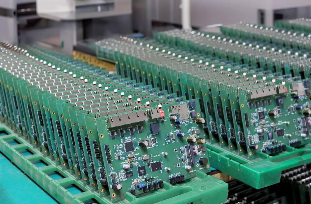
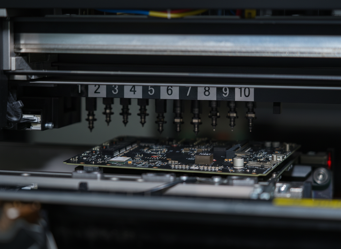
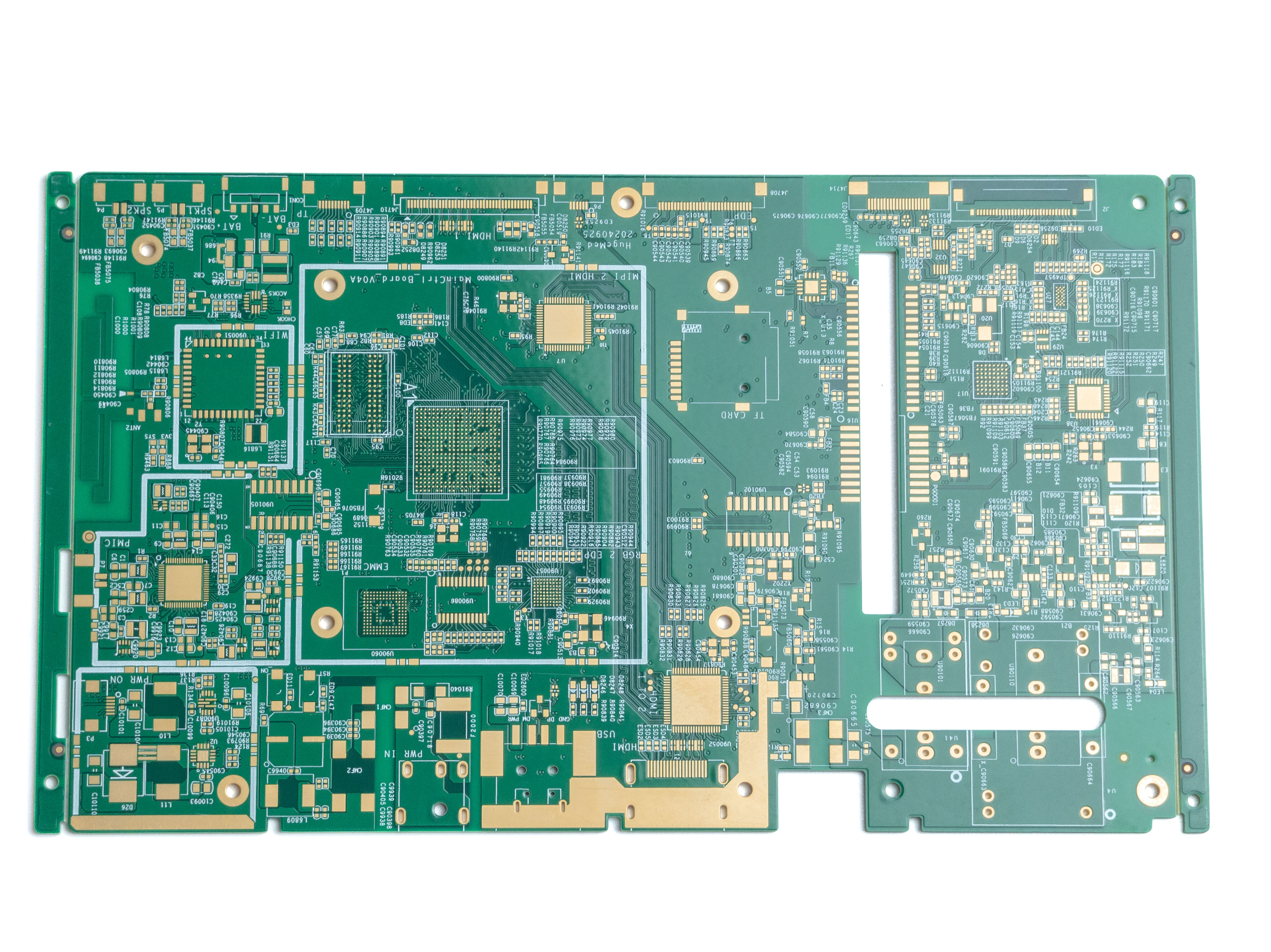
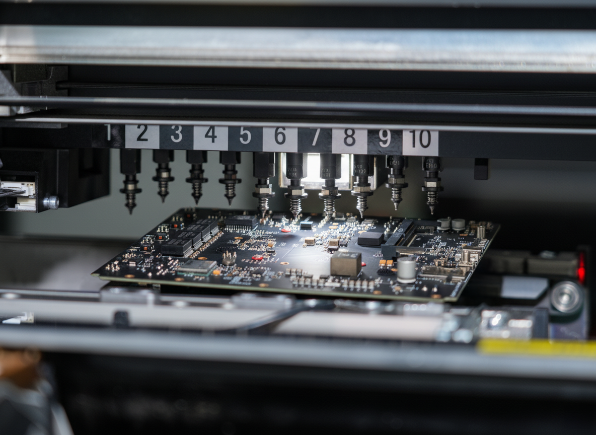
Designing a PCB circuit board is a crucial process that combines technical expertise with modern engineering principles. The process begins with schematic design, where engineers create a detailed electrical diagram of the circuit using specialized software like Eagle, KiCad, or Altium Designer. This initial stage involves careful component selection and placement planning. Following the schematic design, the next phase involves converting the electrical diagram into a physical layout, considering factors such as signal integrity, power distribution, and thermal management. Layer stackup planning is essential, determining how many layers the PCB will have and their purposes. Component placement requires strategic thinking, ensuring optimal signal paths while maintaining proper spacing for manufacturing. The routing phase involves creating copper traces to connect components, following design rules for trace width, spacing, and impedance control. Design verification includes running DRC (Design Rule Check) and ERC (Electrical Rule Check) to ensure manufacturing feasibility and electrical functionality. Modern PCB design also incorporates considerations for EMI/EMC compliance, thermal management, and manufacturing processes like surface mount or through-hole technology. The final steps include generating manufacturing files (Gerber files) and documentation for production.