Quick Links

Home > PCB Manufacturing > Printed Circuit Board > Rigid Flex PCB
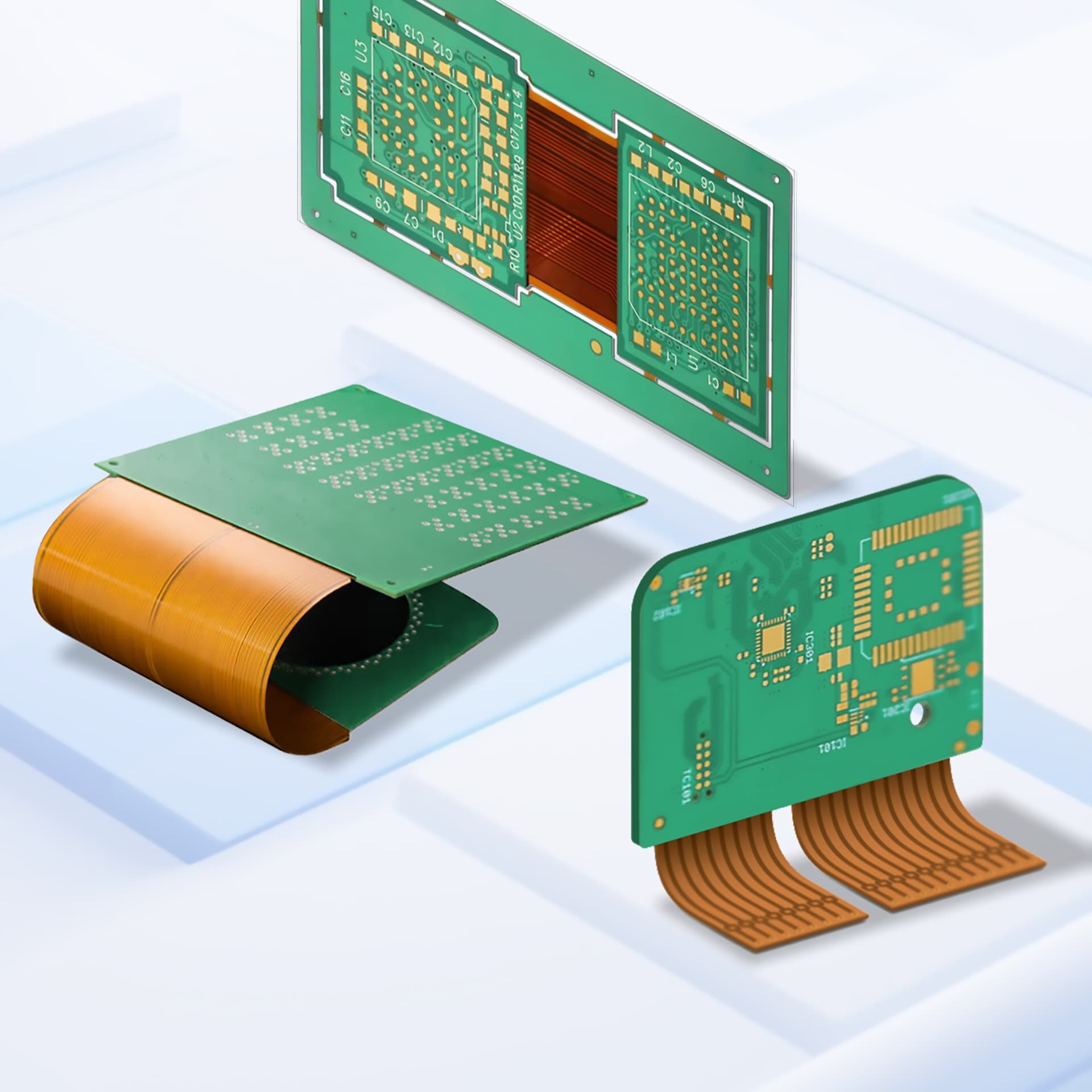
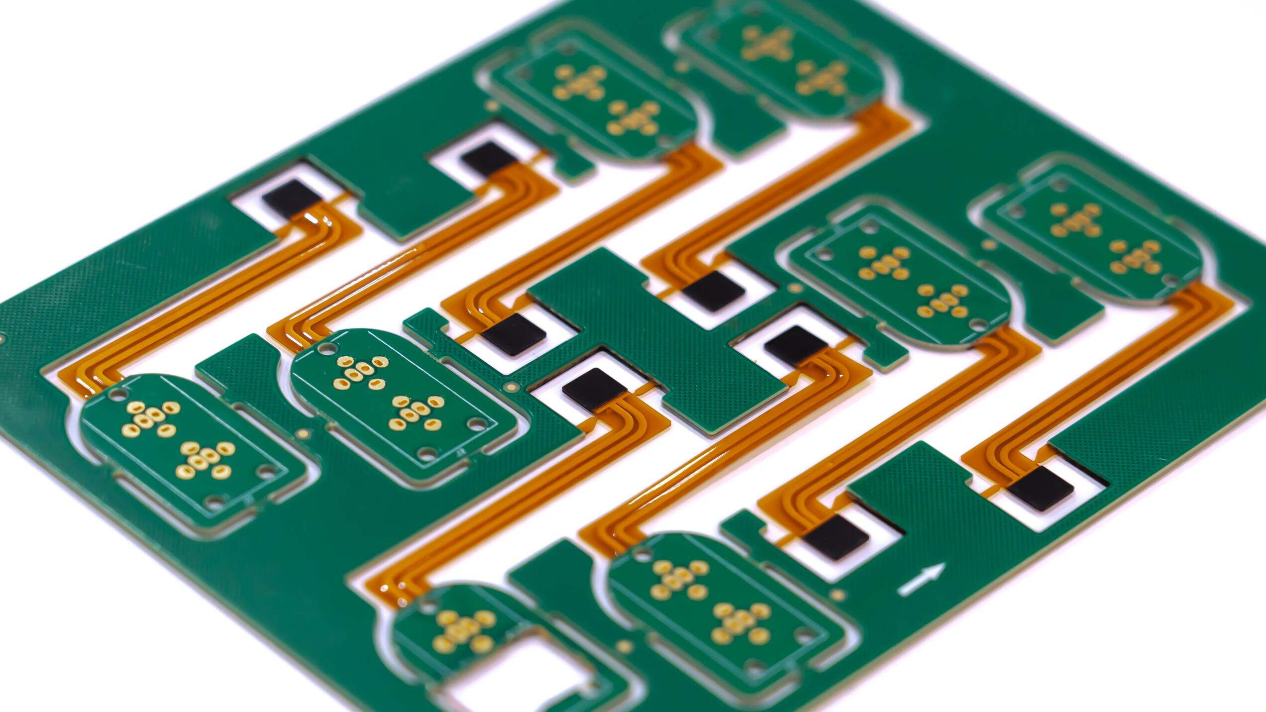
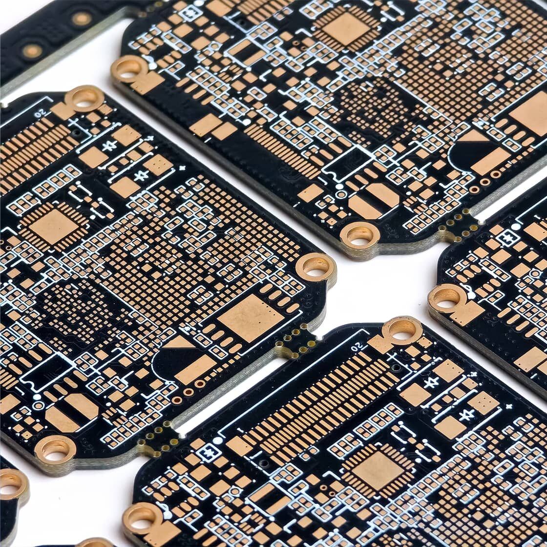
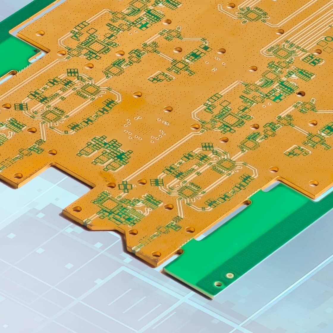
Rigid-flex PCBs are a new type of PCB that combines the characteristics of both rigid and flexible PCBs. Using polyimide as the primary substrate, these PCBs are bendable and flexible, adapting to complex shapes and tight spaces. They are ideal for military equipment, aviation equipment, wearable devices, cameras, smartphones, smartwatches, drones, and more.
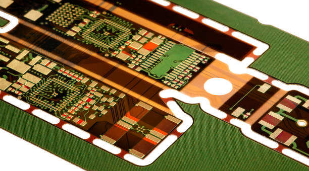
Rigid-flex PCBs, as the name suggests, are essentially circuit boards that combine rigid and flexible circuit boards. They offer excellent bendability and flexibility, making them widely used in medical devices, military equipment, aerospace, cameras, and smartphones. Polyimide is more flexible than FR4, with a dielectric constant (Dk) between 3.0 and 3.5, while FR4 typically ranges from 3.5 to 4.0. Common polyimide materials include Nelco and Rogers, but Kapton is often used for pure flexible boards.
Rigid-flex PCBs are generally categorized into the following three types:
1. Single-Sided Rigid-Flex: This is the simplest rigid-flex PCB, consisting of a conductive copper layer connected to a flexible substrate via drilled holes, and protected by a polyimide coverlay.
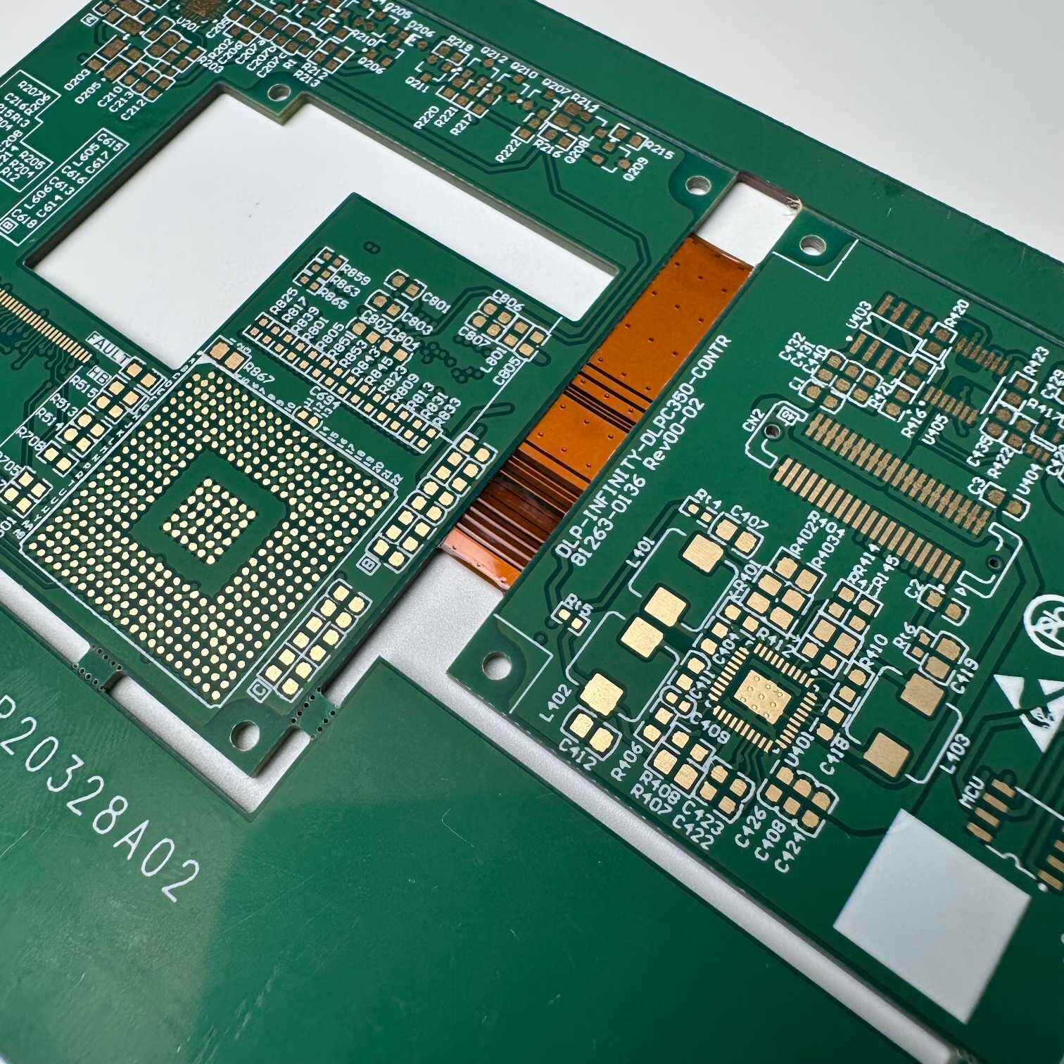
2. Double-Sided Rigid-Flex: This has two conductive layers, with through-holes (PTHs) providing electrical connections between layers.
3. Multi-Layer Rigid-Flex: This has more than two conductive layers. PTHs provide electrical connections between layers, making it more complex to manufacture, but it is ideal for applications such as high-density wiring, crosstalk mitigation, and impedance control.
Compared to rigid PCBs, rigid-flex boards have the following advantages:
1. Adaptability to complex environments: For example, aerospace equipment must withstand extreme environments. Rigid-flex boards use polyimide to cover the conductors, effectively improving their environmental endurance.
2. Compact size and weight: The military has strict requirements on size and weight. Rigid-flex boards can adapt to various small and micro structures, thus reducing size and weight.
3. Strong shock and vibration resistance: They can withstand strong impacts without damage.
4. Reusability: Rigid-flex boards can be folded up to 100 times without damage.
5. 3D design capabilities: They can be designed into three-dimensional shapes to meet different application requirements.
6. Extremely durable and long-lasting: Because they are impact-resistant, they can be used for a long time without breaking.
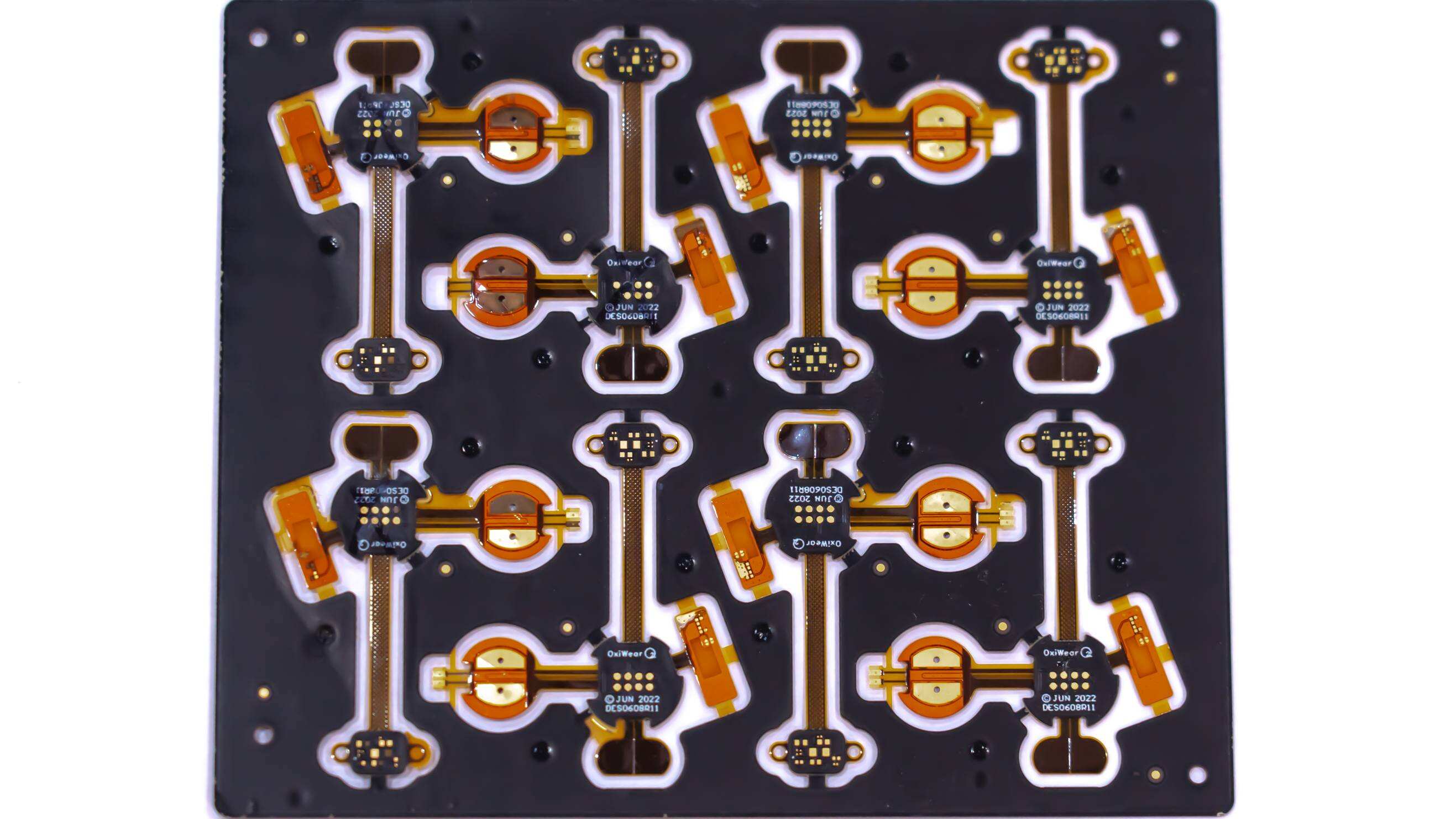
1. Medical devices: such as wearable protective equipment, cardiac compressors, and blood testers. Rigid-flex PCBs offer excellent resistance and a compact size.
2. Mid- and low-end consumer electronics: such as small mobile phones, mini computers, and children's watches, among other small, complex products.
3. Aerospace: such as small drones, spacecraft, space equipment, and Mars rovers.
4. Military: such as defense systems, missiles, atomic bombs, and aircraft artillery.
5. Automotive electronics: such as control panels and built-in navigation systems.
6. Intelligent robots: various AI robots.
When designing a rigid-flex PCB, pay special attention to the following design parameters:
1. Calculate the PCB's bend radius appropriately: The bend radius must be within a reasonable range, otherwise damage may occur.
2. Determine the number of bends: Determine whether the PCB will be static (bend only once) or dynamic (bend repeatedly multiple times).
3. Material selection: Polyimide is recommended for the flexible area, and FR4 for the rigid area.
4. The PTH should be at least 0.5mm away from the bend.
5. Avoid 90° bends, as this can easily break.
6. Do not use PTH in the flexible area or drill holes in the bend.
7. Avoid excessively hot environments, as this product is very heat-sensitive.
8. The impact of the stackup structure on performance: Pay attention to the alignment of each layer, as this will affect the stability and reliability of the rigid-flex PCB.
Always follow IPC 6013 standards.
1. Schematic Design: Engineers divide the board into rigid and flexible areas according to the IPC 6013 standard and design the board first.
2. Material Selection: Kapton/polyimide is selected for the flexible portion, and FR4 is selected for the rigid portion.
3. Lamination: Lamination is performed at high temperatures, but attention must be paid to strength.
4. Drilling and Plating: The stacked boards are drilled and electrified.
5. Component Installation: Component soldering is completed through SMT, soldering, and reflow soldering.
6. Testing and Quality Inspection: Multiple product inspections and quality assurance are performed.
1. While more expensive than FR4, assembly efficiency is higher.
2. Once this product is adopted, overall costs are lower.
3. High-volume production can lower our average cost.
4. To avoid incurring higher costs during prototyping, budgeting should be done in advance.
Feature |
Capability |
| Material Thickness |
Rigid part: 0.8~1.0mm, also 0.295±0.052mm Flexible part: Polyimide (PI) 12.5~75um |
| Trace Width & Spacing | Rigid-flex PCB: typically 4mil/4mil or 3mil/3mil |
| Minimum Hole Size | 0.2mm |
| Flex Bend Radius Design |
Single-side flex: ≥ 6× thickness Double-side flex: ≥ 12× thickness |
| Dynamic Bending Cycle | ≥100,000 cycles without open circuit |
| Lamination Process | Thermal expansion control, specialized lamination equipment; includes FPC/FR-4 |
| Surface Finish | Chemical gold plating |
Choosing a high-quality supplier is crucial, and we are a reliable and trustworthy supplier.
1. Our products are certified to ISO9001 and QS9000 quality systems, with strict quality control throughout the entire production process.
2. Highly affordable. Rigid-flex PCBs are expensive, so we offer very competitive pricing to help customers reduce costs and increase profits.
3. With over 23 years of PCBA experience and rigorous production standards and processes, we guarantee reliable and stable product quality.
4. Our experienced technical team can address various rigid-flex PCB design issues from the very beginning, alleviating customer concerns.
Surface Finish
Sideplating
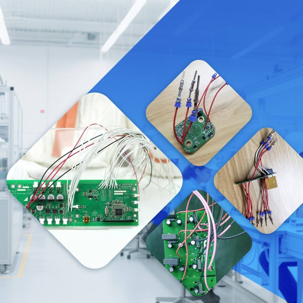
Cable Assembly
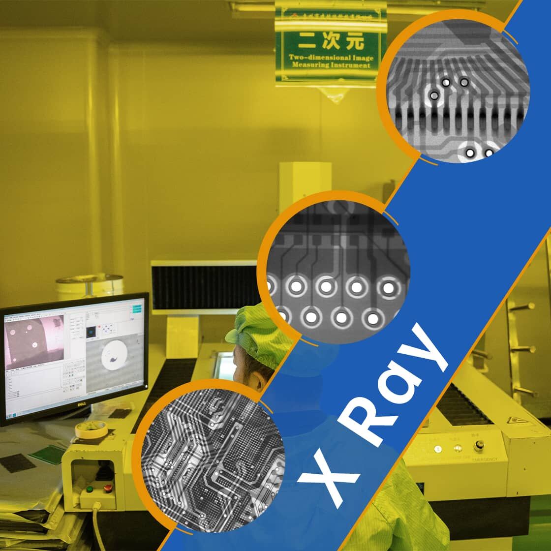
PCB X Ray