
 EN
EN
Every PCB that moves through a production line must be verified before it reaches the end user. Whether a PCB is a simple single-layer board or a complex multi-layer PCBA assembly, standard testing ensures that each PCB performs as intended. Without proper PCB testing, defective boards can cause system failures, safety hazards, and costly returns. Understanding the types of standard testing applied to a PCB helps engineers, procurement teams, and quality managers make better decisions throughout the production process.
A well-tested PCB is the foundation of any reliable electronic product. PCB manufacturers rely on a combination of visual, electrical, and functional testing methods to catch defects at different stages. Each PCB testing method targets a specific type of fault, from solder joint issues to trace continuity problems. This article walks through the core standard testing categories used in PCB and PCBA production, so you know exactly what to expect and what to require from your PCB supplier.
Visual and Optical PCB Inspection Methods
Manual Visual Inspection of PCB Boards
Manual visual inspection is the most basic form of PCB testing. A trained technician examines each PCB under magnification to identify surface defects such as solder bridges, missing components, misaligned parts, and PCB trace damage. While manual inspection is cost-effective for low-volume PCB production, it is prone to human error and becomes impractical for high-density PCB assemblies. Most manufacturers use it as a first-pass check before applying automated PCB testing tools.
Automated Optical Inspection for PCB Quality
Automated Optical Inspection, commonly called AOI, is a key PCB testing method used in modern PCBA lines. An AOI machine scans the PCB surface using high-resolution cameras and compares the captured image against a reference PCB design. AOI PCB testing can detect solder defects, component placement errors, polarity reversals, and PCB pad contamination at high speed. AOI is especially valuable for PCB surface-mount assemblies where manual inspection is unreliable. Most PCB manufacturers integrate AOI as a standard PCB testing step after reflow soldering.
Electrical PCB Testing Methods
In-Circuit Testing for PCB Assemblies
In-Circuit Testing, or ICT, is one of the most thorough electrical PCB testing methods available. ICT uses a bed-of-nails fixture to make direct contact with test points on the PCB. Through these contact points, ICT PCB testing measures resistance, capacitance, inductance, and checks for short circuits or open circuits on the PCB. ICT is highly effective at detecting component-level faults on a populated PCB. However, ICT requires custom fixtures for each unique PCB layout, which adds to setup cost, especially for new PCB designs.
Flying Probe Testing for PCB Validation
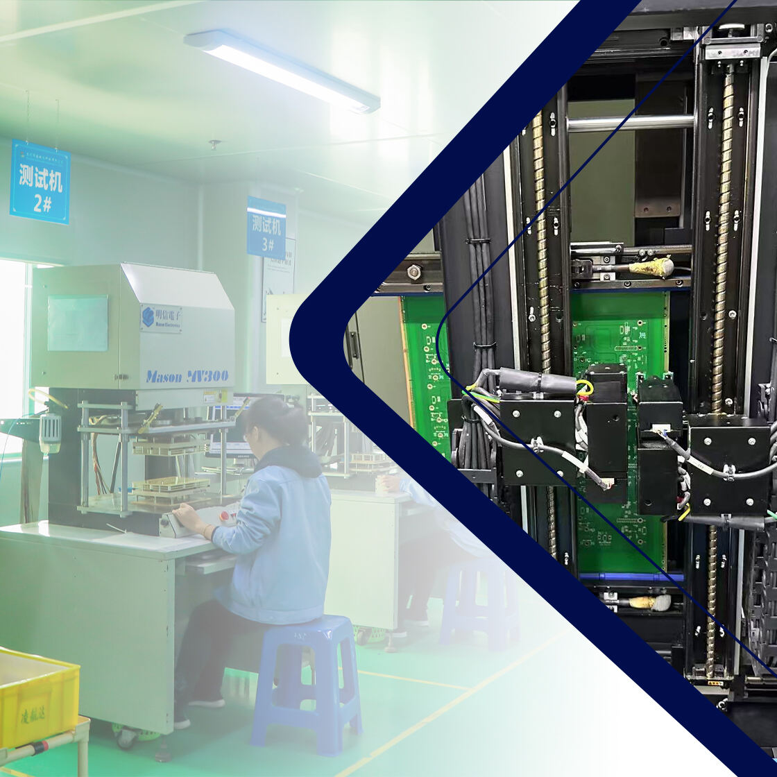
Flying probe PCB testing is a flexible alternative to ICT, particularly useful when a PCB is in the prototype stage or produced in low volumes. Instead of a fixed fixture, flying probe PCB testing uses movable probes that navigate across the PCB surface to contact test points electronically. Flying probe PCB testing checks for open circuits, short circuits, and component values without requiring a dedicated fixture. While flying probe PCB testing is slower than ICT, it offers significant cost savings for small-batch PCB production runs. Many PCB buyers request flying probe testing for prototype PCB validation before committing to full production.
PCB Continuity and Hi-Pot Testing
Continuity testing verifies that all conductive paths on a PCB are properly connected and that no unintended shorts exist. This PCB test is typically performed on bare boards before component assembly. High-potential testing, or hi-pot PCB testing, applies elevated voltage between PCB conductors to verify that insulation can withstand operating conditions without breakdown. Hi-pot PCB testing is particularly important for PCBs used in power electronics, medical devices, and industrial control systems where electrical isolation is critical.
Functional and Advanced PCB Testing Approaches
Functional Circuit Testing of PCB Assemblies
Functional testing, often called FCT, evaluates whether a completed PCB assembly actually performs its intended electronic function. During functional PCB testing, the PCB is powered up and signals are applied to simulate real operating conditions. The PCB outputs are measured and compared against expected performance criteria. Functional PCB testing validates the entire PCB assembly as a working unit rather than checking individual components in isolation. It is especially important for complex PCBs used in communication systems, automotive electronics, and industrial automation equipment.
X-Ray Inspection and Boundary Scan PCB Testing
X-ray inspection is an advanced PCB testing method used to examine solder joints that are not visible from the outside, such as those beneath BGA components on a PCB. X-ray PCB testing reveals voids, bridging, and insufficient solder in hidden joints that would otherwise escape detection. Boundary scan PCB testing, also known as JTAG testing, is another advanced approach that uses embedded test logic within PCB-mounted integrated circuits. Boundary scan allows engineers to test PCB interconnects and component pin connections without physical probe access. Both methods are increasingly standard for high-reliability PCB applications in aerospace, defense, and medical industries.
FAQ
What is the most common PCB testing method used in PCBA production?
AOI, or Automated Optical Inspection, is among the most widely used PCB testing methods in PCBA production. It is fast, accurate, and integrates easily into standard PCB assembly lines after reflow soldering. Most PCB manufacturers apply AOI as a mandatory step in their quality control workflow.
Is flying probe testing suitable for high-volume PCB production?
Flying probe PCB testing is best suited for prototype and low-volume PCB runs because it does not require a dedicated fixture. For high-volume PCB production, ICT is generally preferred since it offers faster throughput. Many manufacturers use flying probe testing to validate PCB designs early, then switch to ICT for mass production.
Why is functional testing important even after other PCB tests pass?
Other PCB tests such as AOI and ICT verify individual PCB attributes like solder quality and component values, but they do not confirm that the PCB works as a complete system. Functional PCB testing powers up the assembly and tests real operational behavior. This makes functional PCB testing the final safeguard before a PCB product ships to the customer.