 EN
EN
Understanding reflow soldering processes is essential for anyone involved in surface-mount technology assembly. Whether you are designing a PCB for the first time or optimizing an existing production line, reflow soldering processes define the quality, reliability, and throughput of your finished boards. From solder paste application to final cool-down, every step demands precision and a clear understanding of thermal dynamics.
Reflow soldering processes are the backbone of modern SMT production. Unlike wave soldering, which suits through-hole components, reflow soldering processes are specifically engineered for surface-mount components that require controlled heat exposure to form reliable solder joints. A well-executed reflow soldering process reduces defects, improves joint consistency, and supports high-density PCB designs that modern electronics demand. This guide walks through every critical stage so you can apply these techniques with confidence.
Core Stages of Reflow Soldering Processes
Solder Paste Application and Component Placement
Every successful execution of reflow soldering processes begins with accurate solder paste deposition. A stainless-steel stencil is aligned over the bare PCB, and paste is pushed through apertures using a squeegee blade. The paste volume, composition, and print consistency directly influence how well reflow soldering processes perform downstream. Too little paste leads to weak joints; too much causes bridging defects that are costly to rework.
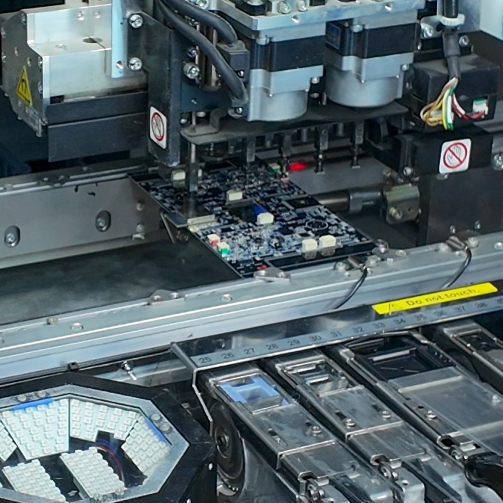
After paste printing, a pick-and-place machine positions surface-mount components onto the paste deposits with high speed and accuracy. The tacky nature of solder paste holds components in place before the board enters the oven. Reflow soldering processes rely on this mechanical stability to ensure components do not shift during heating. Any misalignment at this stage will be preserved — and possibly worsened — once the solder melts and reflows.
Thermal Profile Design in Reflow Soldering Processes
The thermal profile is the single most important variable governing reflow soldering processes. A standard profile consists of four zones: preheat, soak, reflow, and cooling. Each zone controls temperature ramp rates, peak temperatures, and time above liquidus. Poorly designed profiles are the primary cause of defects such as tombstoning, solder balling, and cold joints in reflow soldering processes.
During preheat, the board temperature rises gradually — typically at 1 to 3 degrees Celsius per second — to avoid thermal shock to sensitive components. The soak zone stabilizes the temperature across the entire board, ensuring flux activation is complete before the peak reflow zone. In reflow soldering processes using lead-free alloys such as SAC305, peak temperatures typically reach between 235 and 250 degrees Celsius. Maintaining these precise conditions is what separates reliable reflow soldering processes from defect-prone ones.
Oven Types and Their Impact on Reflow Soldering Processes
Convection Reflow Ovens
Convection reflow ovens are the industry standard for executing reflow soldering processes at scale. These ovens use heated air or nitrogen gas forced through nozzles to transfer thermal energy uniformly across the PCB surface. Nitrogen atmosphere ovens reduce oxidation during reflow soldering processes, which is especially important for fine-pitch components and BGAs where joint inspection is difficult after assembly. Multi-zone convection ovens give engineers the flexibility to tune each zone independently, enabling highly optimized reflow soldering processes.
Vapor Phase and Infrared Reflow Methods
Vapor phase reflow is an alternative approach within the broader family of reflow soldering processes. It uses the latent heat of a vaporized fluid to heat the PCB, providing exceptionally uniform temperature distribution. This method is valuable for reflow soldering processes involving complex assemblies with components of varying thermal mass, where convection ovens may struggle to heat all areas evenly. Infrared reflow, while older, is still used in some reflow soldering processes for cost-sensitive or low-volume applications, though it requires careful management of selective heating effects on different board materials.
Common Defects and Quality Control in Reflow Soldering Processes
Identifying and Preventing Reflow Defects
Defect prevention is a central concern within reflow soldering processes. Tombstoning — where a component stands upright on one pad — occurs when reflow soldering processes create uneven wetting forces on small passive components. This is typically caused by imbalanced pad designs or inconsistent paste deposits. Head-in-pillow defects in BGA packages arise when reflow soldering processes fail to achieve full solder coalescence due to warpage or insufficient peak temperature. Solder bridging results from excess paste volume combined with reflow soldering processes that push molten solder beyond pad boundaries.
Automated optical inspection, or AOI, and X-ray inspection are standard tools used to evaluate the output of reflow soldering processes. AOI examines visible joint geometry and detects surface-level defects quickly. X-ray inspection is critical for reflow soldering processes involving area-array packages where joints are hidden beneath the component body. Combining both inspection methods ensures that reflow soldering processes meet the quality standards required by industries such as automotive, medical, and aerospace electronics manufacturing.
Process Optimization Strategies
Continuous improvement of reflow soldering processes involves profiling each new board design before full production runs. Using thermocouple-equipped profiling boards, engineers measure actual temperatures at multiple locations to validate that reflow soldering processes align with the intended thermal profile. Statistical process control applied to paste inspection data and AOI results helps identify trends before they become yield problems. The best-performing reflow soldering processes are those that treat thermal profile management as a living document, updated whenever board design, component mix, or alloy specification changes.
FAQ
What is the purpose of the soak zone in reflow soldering processes?
The soak zone in reflow soldering processes serves two main functions: it equalizes temperature across the entire board assembly and activates the flux in the solder paste. Proper flux activation removes oxidation from pad surfaces and component leads, enabling clean solder joint formation when the board enters the peak reflow zone. Skipping or shortening the soak zone in reflow soldering processes often leads to poor wetting and increased void rates in finished joints.
How does lead-free solder affect reflow soldering processes?
Lead-free solder alloys require higher peak temperatures in reflow soldering processes compared to traditional tin-lead formulations. This places greater thermal stress on components and PCB substrates, making precise thermal profile design even more critical. Reflow soldering processes using lead-free alloys must balance achieving full liquidus with avoiding damage to heat-sensitive devices. Nitrogen atmosphere ovens are more commonly used in lead-free reflow soldering processes to prevent oxidation at these elevated temperatures.
Can reflow soldering processes be used for through-hole components?
Yes, a technique called intrusive reflow or pin-in-paste allows reflow soldering processes to solder certain through-hole components alongside surface-mount parts in a single oven pass. Solder paste is printed into the through-holes before component insertion, and reflow soldering processes then melt the paste to form the joint. This approach works well for connectors and other through-hole parts with leads that can tolerate reflow temperatures, streamlining production by reducing the need for separate wave soldering operations.